Geometry: Caulk, T-Junctions, Overdraw
It's time to cover some of the basic geometry based optimizations that you can do to improve performance. This section will deal primarily with general best practices though it is up to the level designer to decide how to apply them to each case. What causes a greater performance loss: lowering overdraw at the cost of increasing the polycount of the scene, or vice-versa? The answer is usually a careful balance between the two, and understanding the concepts will allow you to make the best decisions.
Caulk
If you have been around the id Tech level editing community for any time at all, you've probably heard someone (myself being a likely candidate) lecturing someone else about the use of caulk, and with good reason. Caulk is one of the easiest ways to maintain good performance in any level and its use should become second nature to any level designer.
Caulk is a shader, a small script file that tells the engine how to treat a surface, with what properties, and how it will look. Caulk only exists as part of the gamepack SDK, it does not have to be distributed with the game since it is only used by the GtkRadiant editor and the Q3Map2 compiler. This is the contents of a caulk shader:
textures/common/caulk
{
	surfaceparm nodraw
	surfaceparm nolightmap
	surfaceparm nomarks
}
It's quite simple, the first line describes the name of the shader, the contents between the curly brackets tells the engine the properties of the shader. Caulk does not draw anything to the frame buffer as it has no texture, it does not generate a lightmap, and it does not leave marks on its surface when you shoot it or otherwise. It also has a few implied properties that are the default to any normal brush: it is solid (player movement will be blocked, weapons will hit it, bots will see it as a wall), and it casts shadows.
It is due to these properties that makes caulk important to performance. Any surface that draws anything to the frame buffer has a performance cost to it, even if the surface is see-though (because the game still draws the see-though alpha-channel pixels of the texture to the frame buffer). A caulked surface has no textures drawn on it, no lightmap, the engine doesn't even draw the polygon of a caulked surface. Applying caulk immediately drops the polycount of your scene since unseen faces are no longer rendered.
So for any surface that can not be seen by the player, you can apply caulk to prevent it from being rendered. Apply caulk on the rear faces of any brush, the coplanar surfaces between brushes, even on surfaces that are too high up to be seen, or on places where the player can't get to. Most seasoned level designers have a habit of selecting an entire brush and texturing it entirely of caulk. Then only selecting and texturing the faces which can be seen. This ensures that you don't miss any hidden sides of a brush. Caulk is your friend, use it often.
T-Junctions
A T-junction (or T-junc) is a small crack between the edges of polygons where a vertex intersects an edge often (but not always) in the form of a letter "T". This often causes a visual artifact commonly referred to as "sparklies", which look like small flickering pixels along an edge. Q3Map2 does try to solve for T-juncs, but doing so automatically will often results in a high number of generated polygons. A little manual brush slicing allows you to solve both problems.
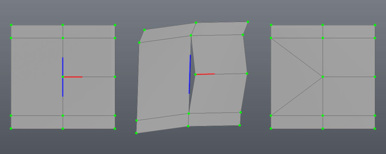
Below is an actual example, a collection of polygons with vertexes highlighted in green. On the left, the red line highlights an edge that intersects another edge highlighted in blue. It may look okay right now, but what you can't see is the tiny fracture between the polygons. The tiny fracture is what causes the "sparklies" effect. This becomes apparent (center) when we stretch the polygons and you can see a hole appears between the polygons where the red edge meets the blue edge. This is because the vertex at the end of the red edge does not have an accompanying vertex on the blue edge to weld with. The problem can be solved by splitting the polygons so that the blue edge has an extra vertex point to weld with the red edge as seen on the right.
Most of the time, Q3Map2 will automatically split surfaces to create additional vertexes for welding. It doesn't always do this intelligently, it basically traces a cut to the nearest vertex or sometimes places a new vertex right in the middle of a polygon. A little manual polygon management with the clipper tool goes a long way to solve these cases.
Another issue has to do with patch mesh curves, they cannot be split by Q3Map2 to solve for T-junc errors, so you have to pay special attention to where the major control points of patches meet with other patches and brushes.
Overdraw
Overdraw occurs when an object is drawn to the frame buffer, and then another object is drawn on top of it. The time spent drawing the first object was wasted because it isn't visible. Ideally, overdraw should be avoided as much as possible while balancing other considerations like polycounts.
In addition to performance drawbacks, overdraw some situations can also cause "z-fighting" visual artifacts, particularly with large draw distances and expecially if running the game in 16-bit mode.
Overdraw can also occur when working with shaders with more than one renderable texture. With these multipass shaders, for each texture drawn an extra rendering pass is added to the frame buffer, doubling the fillrate. When working with shaders with multiple texture stages and transparencies (like grates), this can quickly stack up with large performance drawbacks!